Internal Gutter Overflows
An internal gutter needs an overflow – it’s as simple as that. To be more specific, a gutter needs to be able to overflow in a ‘controlled’ manner. It’s just a question of where it overflows to.
BY PAUL STANLEY-BODEN, VICE-PRESIDENT, ROOFING ASSOCIATON OF NZ (RANZ)
The rules* are: an internal gutter shall be fitted with overflow outlets, which drain to the exterior of the building. That is a clear and unambiguous statement. You must have overflows in a gutter. The reason for this goes back to the purposes of the building code clause E1 – surface water- to protect people and property from harm or damage from water entering the building.
There are two main reasons why an internal gutter would fill up with enough water to overflow into a building; the more common one being a blocked outlet, the other being extreme rainfall, enough to overwhelm the discharge capacity of the gutter. Given the recent extreme weather events that NZ has experienced, the second option may become less of a rarity.
Looking a little deeper into the E1*, we find that the top of the overflow shall be at least 50mm below the top of the gutter. Given the wide variety of internal gutter designs, it is unclear how this is applied practically. It is best to interpret the top of the gutter as the lowest termination point of the membrane that could overflow into the building (figure 1). Bearing in mind also that E2** states that the internal gutter has a minimum freeboard of 30mm, you need to avoid the situation where an overflow is level with the bottom of the gutter (because it is now a drain).
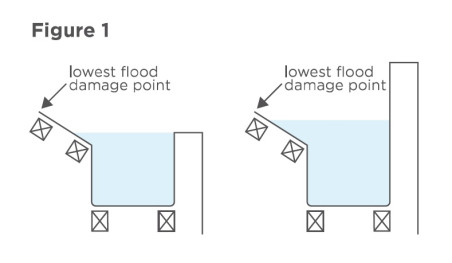
The next requirement is that the overflow needs to be the same size or bigger than the outlet. Pretty obvious. If the outlet is blocked, the overflow must be able to step up and carry the full outlet capacity. And, in an extreme weather event, you have effectively doubled the discharge capacity.
Lastly, E1 would like you to put the overflow where it can be seen and where it can’t cause additional harm. It’s important that the building’s occupants can see an overflow working so that they are alerted to a possible problem with the gutter or outlet or to be more pragmatic about it – know it’s time to clean out the gutters.
The ‘additional harm’ request relates to E1 and surface water. It is preferable that the water discharging from an overflow runs clear of the building. Having prevented the overflow water from coming through the ceiling, it’s also a good idea to avoid it coming through the front door! So far, so good.
The challenge to the roofer is not so much the requirements of the building code but dealing with the practical application of said requirements. There are several common ‘constraints’ to meeting your obligations:
• Often, there are no overflows drawn on the plans. This usually leads to the inevitable on-site debate with a builder about whether they’re needed. The best response here is, “Yes, they are, and it’s easier to do it now than when it’s picked up during a later inspection.”
• “We don’t need an overflow because there’s one on the rainwater head.” Wrong. The overflow on the RWH deals with a blockage in the RWH outlet and prevents backflow into or under the gutter outlet.
• Aesthetics #1. “The architect wants the overflow(s) hidden
somewhere, like in the rain head.” As we have discussed earlier, one
of the functions of an overflow is as an early warning of potential
problems, which can’t happen if you hide it.
• Aesthetics #2. “I don’t want a big ugly pipe sticking out of the wall. Can we make it really small?” No. But there is nothing to say you can’t put in multiple, smaller overflows. However, you need to consider discharge capacity. A single 100mm x 50mm pipe has less sidewall area and less ‘drag’ than two 50mm x 50mm pipes. It is also worth remembering that the smaller the outlet, the greater the probability it will block. Suddenly, your double-overflow option starts to look more like three or four. The better solution here is to cover the ‘big ugly’ with a shroud or grill to look like a light or a vent. Funny how vents or lights scattered across a wall are aesthetically pleasing, whereas your flood preventor is not!
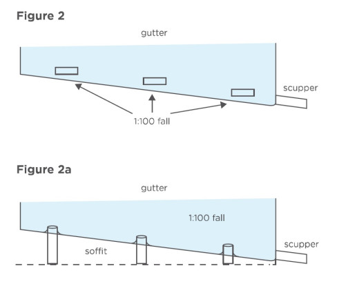
Many of the aesthetic concerns can also be overcome with some forward planning. There are several ways to deal with the overflow ‘problem’. For example, the type and location of the overflow in the gutter is often optional. The overflow can be anywhere along the length of the gutter, provided you set heights correctly (Figure 2). It can also be in the floor of the gutter rather than the side (Figure 2a). This could allow you to drop it through the soffit and disguise it.
Types of outlets
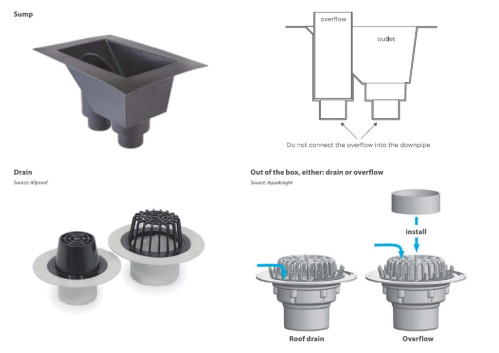
Sumps, scuppers or drains are the three main gutter outlet accessory options. The type of outlet will often determine the kind of overflow, in that sumps and drains can have overflow versions.
Sumps are installed into the base or floor of the gutter and usually include an overflow. The height of the entry point of the overflow is set to take the excess flow should the outlet block or become overwhelmed. This height setting must also prevent water from entering the overflow system under ‘normal’ conditions. If not, the overflow outlet will often drip.
Water discharging from the overflow pipe must be visible. If the overflow is connected to the downpipe, it is no longer performing the required functions of an overflow. In this situation, it is only a backup outlet, and an alternative overflow must be installed.
Drains are also installed into the base of the gutter for obvious reasons. However, it is possible to use the same accessory in the wall of the gutter as an overflow. Alternatively, there are overflow variants that can be installed in the base, which have an in-built ‘riser’ for the overflow. The drain/overflow combos are ideal if the gutter is visible and aesthetics are a factor.
Sealing the riser into the base is a good idea to prevent small amounts of surface water from dripping through.
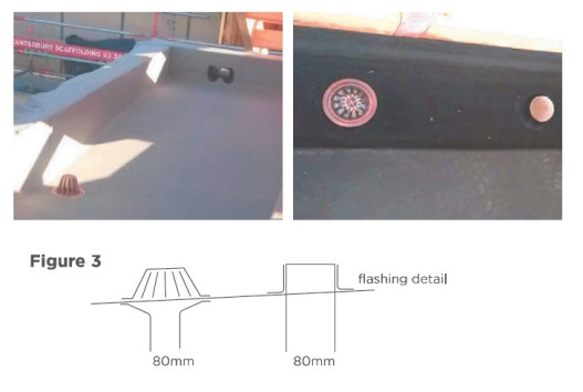
Overflow through the parapet wall
The overflow is set low on the inside wall but at the high (shallow) end of the catchment area. Equally, the overflow could have been installed on the same plane, anywhere along the parapet wall, provided the discharge point was visible and an overflow did not create a nuisance. Note the rectangular overflow used here has a larger capacity than the circular drain.
In this situation, the overflow is the same diameter as the outlet. It is approximately 20mm above the base of the gutter and flashed appropriately (Figure 3).
And then, there is the specific design or alternative solution overflow. In the design below, the gutter has no overflow accessories. The gutter system is designed with the front gutter wall lower than the rear. In the event of a flood, the gutter overflows clear of the building along the entire length of the gutter (Figure 4). Arguably, this is the most robust variant, but it is subject to specific design (for consenting purposes) and will need to consider the run-off implications at the level below.
Remedial work
Extreme weather (i.e. heavy rainfall) typically results in phone calls from clients with gutter leaks. There is a high probability that the problem is a lack of maintenance – the gutter is full of leaves, dead birds, tennis balls, plastic bags, waste materials from the last heat pump service etc. It’s an easy, if not pleasant fix.
Occasionally it is damage (the AC guy again or maybe an over-zealous gutter cleaner) and, again, not usually difficult to resolve. However, sometimes it’s a capacity issue and/or an absence of overflows. An absence of overflows in older constructions is relatively common – possibly due to a lack of plan details. The modern-day consenting authorities, however, are much more enthusiastic about overflows. I suggest you quickly calculate the roof and adjacent wall areas (if applicable***) and refer to Table 5 of E1* to see if the outlet is big enough. If not, you have a slightly bigger remedial task or two on your hands.
Appendices
* from E1 Surface Water, Amendment 11 – 5 November 2020
5.5 Overflow outlets, 5.5.1 All internal gutters
The top of the outlet shall be set at least 50mm below the top of the gutter. The cross-sectional area of the outlet shall be no less than the cross-sectional area of the downpipes (determined by Paragraph 4.2.1) serving the gutter.
COMMENT: An internal gutter overflow outlet should be located to give an early, conspicuous warning to the building occupier that maintenance is required. Also, note that the overflow discharge should be able to run clear of the building.
** from E2 external moisture 8.1.6.1 Internal gutters – internal gutters shall:
a) Be formed with continuous butyl or EPDM strip complying with Paragraph 4.3.9, with no cross-joints in the gutter,
b) Where butyl or EPDM, be a minimum 1.5 mm membrane thickness, or 1.0 mm thickness for gutters less than 1 metre wide
c) Have a minimum slope of 1:100
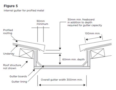
d) Have capacity that meets the requirements of NZBC Clause E1 and have a freeboard depth of at least 30 mm, but in no case have any dimension less than those shown in Figure 5.
Also note that Internal gutter support must be strong enough to support the weight of water when at capacity, and if over 300 mm wide, be able to support foot traffic.
*** Half the area of the wall is added to the roof area.
In the case of a standard double garage attached to the side of a two-storey building, this could increase the catchment area from approx. 50m2 to 85m2.
This article was first published in the RANZ Member magazine, RoofLink® in Winter, 2023.
Membership applications are welcome – see the link here.